 |
| Voltage regulator, XBee, LM335 |
 |
| LM2937ET-3.3 (top), LF33CV (bottom) |
Update 5-15-2011: I was revisiting the voltage regulator wiring as I was beginning the "Direct Actuation Example" in Chapter 6, pages 172 following. It looks like the LD1117V33 is wired the wrong way in Figure 5-6. According to the datasheet the legs are GND, Vout and Vin when viewed from the front. The upper rail for GND in Figure 5-6 is connected to Vout, Vcc 3.3 volts is connected to Vin. It also looks like the capacitor and the hookup wires from the power plug are connected the wrong way. So be careful and double check the whole voltage regulation for this experiment. The text and figures 5-4 and 5-7 seem to be ok. I submitted it to the Errata and got the following answer:
"Unfortunately 3.3V regulators do not have standardized lead arrangements. As the instructions say on page 145, 'The regulator has three legs - typically, ground, output, and input - when viewed from the front (where the writing is). Sometimes these legs are in a different order, so find and check the data sheet if you're not sure!'
Fritzing uses one of the alternate pin arrangements (IGO). We can bring this up with them and redo the diagram in a future printing, but the caution still applies."
Setting up the three XBees is a nobrainer - the AT commands are very well explained in the same chapter so no surprise at all. If you haven't done so it's now time to solder another breakout board for the new XBee. Then everything has to be placed on the breadboards.
 There is little room near the voltage regulator if you take (bigger) capacitors (e.g. suited for higher voltages) - Figure 5-4 looks a bit crowded near the regulator. I took capacitors with a small form factor rated for 16 volts which might be more than enough. Anyway you could place them as suggested in Figure 5-6 (page 149) then you have more room for everything. I'm not sure the capacitors should be very near the regulator, maybe someone out there could answer this question.
Be aware that the resistor connected to the + (middle pin) of the LM335 is 300 ohms and not 300 kohms as described in figure 5-6 and 5-7.The voltage regulator (labeled with "7833") and the temperature sensor are both labeled "U2" in Figure 5-7 - only a minor typo - but you should "cut" the ground connection from Pin1 (XBee) and the voltage regulator. Figure 5-6 shows the correct connections.
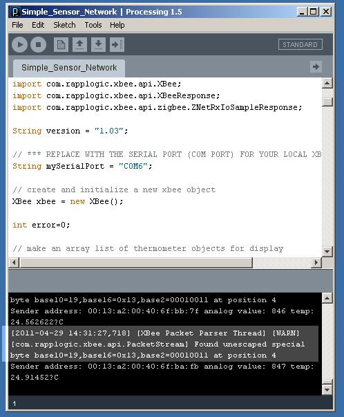 Next is installing "Processing". Everything went fine on my computer and I only had to replace the COM-port entry which is "COMx" (x stands for the port number) in Windows. I had two sensors connected and after starting the Simple_Sensor_Network.pde everything took place like it is described in the book. There was only one error in the lower window: "[XBee Packet Parser Thread] [WARN] [com.rapplogic.xbee.api.PacketStream] Found unescaped special byte base10=19,base16=0x13,base2=00010011 at position 4". The program worked anyway.
One thing you really have to think about if you are planning to use the LM335 is calibrating the sensor. I have five sensors and some are "wrong" up to 3 degrees centigrade. I also had some trouble calibrating the sensors and it looked like they were still shifting after calibrating them. In the past I used to take the (digital 1-wire) DS18x20 temperature sensors - I'm still not sure if there is a way to connect them directly to the XBee and send the data to the coordinator for displaying it on the computer (another new item on my TO-DO-list).
No comments:
Post a Comment