Presentation: Basics, charge and control circuits/ ideas for singe cell lithium rechargeable batteries
Lithium cells are quite powerful
On October 6 I had a short presentation at the Makerspace Attraktor in Hamburg on how to work with rechargeable lithium cells.
A lot of information has to be considered when working with rechargeable lithium cells. Beside the basics, I went into information about the typical charge and discharge characteristics and some circuits and ideas on how to charge and control those cells.
You can find the presentation (pdf in german) here
If you want to stay in touch with new projects or blog entries you can follow me on twitter
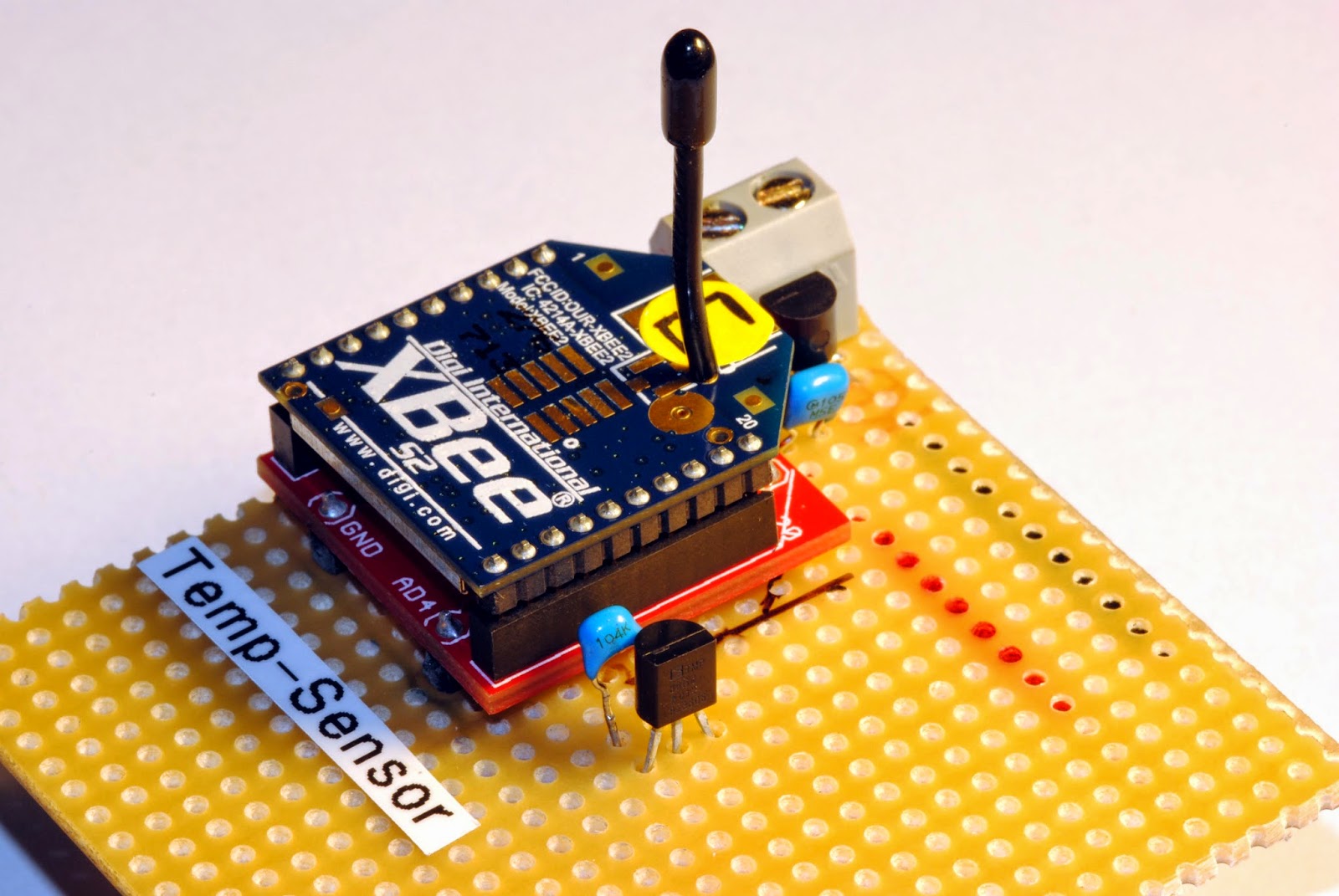
There were some questions over time on how the remote sensors on my XBee network are actually wired up and I discovered that I only showed the sensor as is and never explained the wiring. So now this is done with this post and a breadboard picture made with Fritzing:
Remote temperature sensor with XBee
Hardware
The actual remote sensor has the components just soldered to a stripboard (which works for years now outdoors without any problems). For voltage regulation I use the low quiescent current LDO from Microchip MCP1700-3302E (3.3V, TO-92 style, ~1µA quiescent current consumption). There are 1µF ceramic capacitors both on the raw voltage input and the regulated output (just followed the typical application advice on the datasheet).
The temperature sensor TMP36 is wired to Ground, the Vout is connected to pin 20 of the XBee (AD0/ DIO0/ commissioning button) and Vin is wired to pin 13 (ON/ SLEEP).
The trick with consuming power for the temperature sensor only when the XBee is awake is to wire it to pin 13 (ON/ SLEEP) which is only powered when the XBee is awake.The sensor takes about 50µA when powered and is fast enough to get a temperature measurement while the XBee is not sleeping and takes samples from the AD0-Input (pin 20 XBee).
Temperature sensor on stripboard
My sensors are all powered with three AA cells for now and there is enough room from about 4.8 volts when full and fresh to 3.3 volts when it hits the regulated voltage. The sensor even works below that because I think the supply just gets pulled through the voltage regulator when at or below the regulated voltage.
The circuit draws only about 2.3µA when the XBee sleeps and about 40mA when awake but only for a very short amout of time. So the batteries last about are year or longer.
Software There is not much software involved beside configuring the logic on the XBee. Those are my settings:
SENDER: (REMOTE SENSOR )
END DEVICE
ATID 2001 (PAN ID)
ATDH 0
ATDL 0
ATD0 2 pin 0 in analog mode with TMP36
ATIR 3E8 sample rate 1000 millisecs (hex 3E8)
ATSM 4 sleep mode cyclic sleep mode
ATSN B number of sleep periods (hex B = 12 decimal) ATSP 7D0 sleep period (hex 7D0 = 2000 ms * 10 = 20 seconds)
ATST 7D0 time before sleep 2 seconds (hex 7D0 = 2000 ms)
Output on a custom made display-box for the kitchen with bus schedule
So the sensor is configured to sleep for four minutes (roughly, the oscillator in the XBee circuit seems to be either imprecise or temperature sensitive) then waking up for two seconds, powering the temperature sensor, sampling two times and then go to sleep again. That's all it does. Voila!
There is still room to improve the project. For example one could add an energy harvesting module to the circuit so that no batteries are used to power the device. Another nice feature would be to take a measurement of the actual battery voltage, which could be done with a simple high resistance voltage divider on one of the analog inputs. It might also be clever not to wire the temperature sensor to pin 20 which is also the comissioning button just in case your XBee is reluctant to wake up.
The mystery of the whereabouts of Malaysia Airlines flight MH370 continues and all my thoughts go to the family members having relatives on board of the disappeared Boeing 777-200.
But there is also technical part of the whole story and regardless of the outcome it's worth having a look at the different systems which are involved electronically.
There are four main systems which provide communication between an airplane and the ground. The oldest one, which helped the british army to identify their german counterparts, is the
Primary Radar
High frequent impulses are sent out by a (ground) station into the air and if they are deflected they echo back to the receiver at the (ground) station. The time the signal runs can be calculated and from that the distance and direction of the "object" is derived. Primary radar signals have to be interpreted so it's sometimes not easy to judge if the "object" is a plane or a flock of birds. There are also limits due to the range of the radar waves and other factors like weather.
Some producer of flying (military) objects - stealth planes - even use their outer shape to avoid any de- or reflection of the radar waves.
To support the findings of the passive primary radar most of the planes, helicopters etc. send out an active transponder signal which is termed
Secondary Radar
Where the word "radar" stands for an active transmission of a signal coming from aboard a flying object. Well known as "transponders" the device sends an active signal which can be of different quality. The earliest systems gave an identifier or answer code (aka "Squawk code") so that the signal of the primary radar and the received signal of the transponder could be matched.
Today a system known as "ADS-B" - Automatic Dependent Surveillance - Broadcast - is used in many (commercial) airplanes. Once the systems on the plane are on, ADS-B is also automatically activated. Already on ground the system gets automatically interrogated by ground (radar) stations so that the signals can be matched. But those newer systems not only give an identifier, but also lots of other data like speed, altitude, heading and more. The Boeing 777-200 MH370 is equipped with those systems. The range also depends both on the (height/ distance) of the airplane and the quality of the receiving (ground) station. The frequency of ADS-B is 1090MHz.
Voice Radio Transmissions
Even if many of the processes in aviation are automatically done there is still a lot of live voice communication between pilots an (ground) stations. This is done mostly on VHF (Very high frequency). The normal air radio frequencies are between 108 and 137 MHz. Military often uses other (higher) frequencies. As with all high frequencies the transfer of messages underlies technical constrains like range, weather, power of the sender, height, and receiver sensitivity. So in some parts of the world there still have to be used less sophisticated radio signals to get contact to the ground.
ACARS - Aircraft Communications Addressing and Reporting System
Another active system is known as ACARS - Aircraft Communications Addressing and Reporting System. It does what the name implies - it actively, automatically, un-interrogated sends data live to the ground or up to a satellite. Data can be of any quality - from simple status messages to extensive data reports from systems on the plane. Allmost all commercial aircrafts send those data to their headquarters relayed by radio stations around the world. As allegedly done and reported by the Wall Street Journal the MH370 sent (engine) data for hours into the flight. Depending this is true it is still the question of what quality the data was. -UPDATE Malaysian officials have told there were no ACARS radio transmission after losing contact to MH370. Last ACARS transmissions were at 01:07AM local time - The radio transmissions are done in some of the air band frequencies so they underlie the some constraints as mentioned above. Then there are sensors and radio transmissions more or less independent on the before mentioned systems like the one of the jet engines, which are capable of sending sensor data without using the ACARS system (e.g. http://www.rolls-royce.com/about/our-technology/enabling-technologies/engine-health-management.aspx#sense). Those were of special interest in the MH370 case because there were transmissions long after disappearing of the plane and some attempts of triangulation to get a possible location of it.
In case of an emergency EPIRBs- Emergency position-indicating radiobeacon stations - are automatically activated. They are also constrained in respect to range and especially the time (about 30 days) they are able to send signals. There are a lot of systems for different use cases available (More info: https://en.wikipedia.org/wiki/Emergency_position-indicating_radiobeacon_station).
Finally there are other means of identifying flying objects like satellites which are capable of visual or radio tracking, flying radar/ radio stations like AWACS-planes (Airborne Warning And Control System) and other and more secret ways to identfy objects in the airspace. But those are special ways and normally not involved with commercial aviation.
I'm a lot into 3D-printing the last months so it was quite silent with news in the blog. Staring at plastic building up in layers so thin you can barely see them is very fascinating as it builds up a new dimension one is not used to see. But the plastic material called "filament" for 3D-printers is neither very cheap nor you have a great choice of colors or materials (yet).
Layer as fine as 10 micrometer printed with my Ormerod 3D-printer
So my very new project is building a DIY 3D-filament extruder. Yes, there are already projects like Filabot and Filastruder out there, but I could not find real DIY projects among them.
It happened that I worked as a holiday job at a plastic recycling factory almost thirty years ago, that did exactly what I'm planning to do now - extruding filament from pellet like material. It's a personal challenge to return to this.
It's not only a challenge to build such a machine but also to get it producing high quality materials that print either very thin layers (see photo) or different materials with certain characteristics, that can be easily reproduced in every aspect like quality, diameter etc.
So stay tuned for the developments here.
DIY Project "Print your laser"
I'm also working on printing the 3D-parts for Markus' (same name but not me ;) ) awesome print your laser project, with other people at our Makerspace Attraktor in Hamburg. Markus wants to build a DIY CO2 laser from parts readily available and of course as cheap as possible. At the moment we are testing the end caps for the plasma tube and getting them as airtight as possible.
It's fascinating how 3D-prinitng opens a whole new way to design and produce things like twisted tubes buried into parts which would be impossible to make with conventional and relatively affordable tools like a lathe or CNC milling machine. Of course it's possible to do things like this for quite some time as there a professional and very expensive ways to do this - but DIY-wise and making with low budget is the real new way getting things done.
But it still needs to design the stuff with CAD-programs (lots of open source like OpenSCAD available), prepare it for 3D-printing (like slicing the 3D-models), getting the right materials and troubleshoot the prints for their very application. 3D-printing for everyone is still a bit out there.
In the video (timelapse) above you can see a small part of the end cap for the laser tube printed on my new Ormerod 3D-printer from RepRapPro.