 |
| Remote temperature sensor with XBee |
Hardware
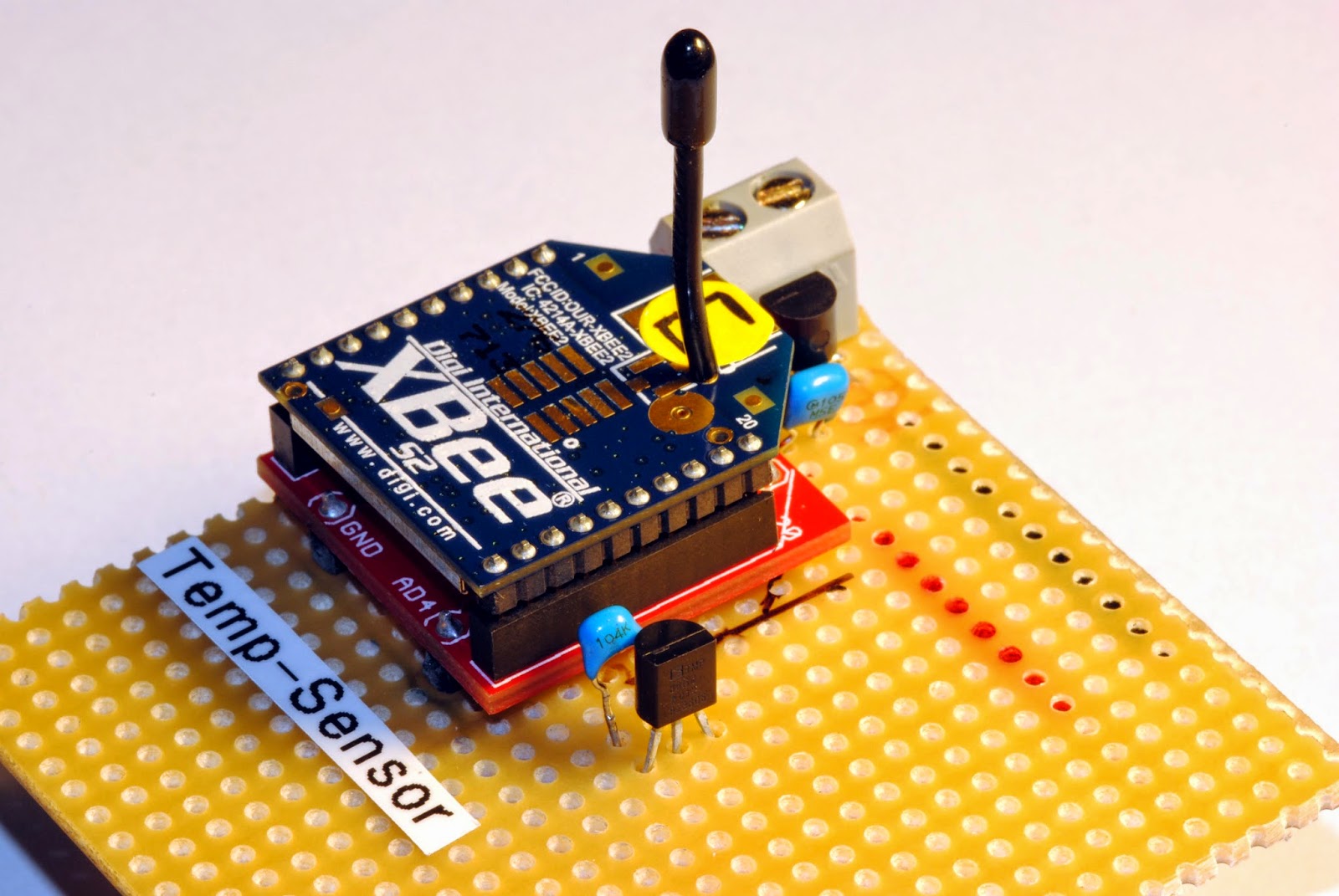
The actual remote sensor has the components just soldered to a stripboard (which works for years now outdoors without any problems). For voltage regulation I use the low quiescent current LDO from Microchip MCP1700-3302E (3.3V, TO-92 style, ~1µA quiescent current consumption). There are 1µF ceramic capacitors both on the raw voltage input and the regulated output (just followed the typical application advice on the datasheet).
The temperature sensor TMP36 is wired to Ground, the Vout is connected to pin 20 of the XBee (AD0/ DIO0/ commissioning button) and Vin is wired to pin 13 (ON/ SLEEP).
The trick with consuming power for the temperature sensor only when the XBee is awake is to wire it to pin 13 (ON/ SLEEP) which is only powered when the XBee is awake.The sensor takes about 50µA when powered and is fast enough to get a temperature measurement while the XBee is not sleeping and takes samples from the AD0-Input (pin 20 XBee).
 |
| Temperature sensor on stripboard |
The circuit draws only about 2.3µA when the XBee sleeps and about 40mA when awake but only for a very short amout of time. So the batteries last about are year or longer.
Software
There is not much software involved beside configuring the logic on the XBee. Those are my settings:
SENDER: (REMOTE SENSOR )
END DEVICE
ATID 2001 (PAN ID)
ATDH 0
ATDL 0
ATD0 2 pin 0 in analog mode with TMP36
ATIR 3E8 sample rate 1000 millisecs (hex 3E8)
ATSM 4 sleep mode cyclic sleep mode
ATSN B number of sleep periods (hex B = 12 decimal)
ATSP 7D0 sleep period (hex 7D0 = 2000 ms * 10 = 20 seconds)
ATST 7D0 time before sleep 2 seconds (hex 7D0 = 2000 ms)
 |
| Output on a custom made display-box for the kitchen with bus schedule |
There is still room to improve the project. For example one could add an energy harvesting module to the circuit so that no batteries are used to power the device. Another nice feature would be to take a measurement of the actual battery voltage, which could be done with a simple high resistance voltage divider on one of the analog inputs. It might also be clever not to wire the temperature sensor to pin 20 which is also the comissioning button just in case your XBee is reluctant to wake up.
simple yet useful daily stuff, thanks for sharing this
ReplyDeletewhat software are you using for this project?
I'm using Atmel Studio/ Arduino IDE for the program code and XCTU to program the XBEE firmware.
ReplyDeleteThis remote temperature sensor sounds great. I'm thinking of buying a humidity sensor for my home. Greetzs
ReplyDeleteCan a pulse oximeter and heart rate monitor be added also, all on pin 13?? I want to monitor temp, oxygen and pulse every 15 minutes.
ReplyDeleteNo, bu you could add them on other XBee pins.
DeleteHi Markus,
ReplyDeleteDo you work as consultant for xbee related projects? If so, I would be interest to know how much you ask. I can send you the details of a project if you are interested.
Regards,
Jose
Sorry Jose, just saw your comment. Yes I'm also working as a hardware developer. Just email me at blogger(at)tradewire.de if you are still interested.
DeleteThis comment has been removed by the author.
ReplyDeleteHi markus, as u mentioned that u hv used Atmel Studio/ Arduino IDE for the program code. But Where is the Atmel controller.
ReplyDeleteI'm not quite sure what you mean by "Where is the Atmel Controller".
ReplyDelete