4/09/2016

Raspberry Pi 3 "Echo"

Building an Amazon Echo similar device out of a Raspberry Pi 3


I recently worked as an electronics hardware developer on a new smarthome system which is designed to have speech recognition as a way of controlling devices.


Over the course of researching soft- and hardware for this purpose while in Silicon Valley I also tested and reverse engineered the "Amazon Echo" - an electronically very well designed device and a huge success for one of the in-house manufactured devices from the electronic commerce and cloud computing company.

The latter also lays the groundwork for Amazon Echo and the speech recognition called "Alexa" utilized in the round tower like gadget. With a price tag of $180 and - more important - not yet available to customers outside the US I was quite happy back in Europe to see a github repo to allow implementing an Amazon Echo similiar device and especially speech recognition on cheap hardware like a Raspberry Pi.

I bought the quite new Raspberry Pi 3 - even if the github repo uses a Pi 2 - expecting some minor issues, what turned out to be true. A big help was to browse the "issues" related to the repo.

In short I avoided to install a new JDK because it already comes with new Raspian Jessie image. I put on the newest version of Node.js, used the WiFi which is onboard with the RasPi3 and tested different microphones because the one suggested on the github repo has some bad reviews. That's basically all I deviated from the original installation instructions, which worked out very well.

After only two hours or so everything was set up without problems. In the video below and for the first tests I used a webcam with an integrated microphone, a Logitech QuickCam Orbit AF, which I had lying around while the dedicated USB microphone was ordered but had not arrived.


Identifying the microphone chipset

The problems began when I got the new USB microphone, a "Lerox USB microphone" ordered - of cause - from Amazon. In the beginning I had barely no success getting "Alexa" recognizing my commands. I had pulsing sounds (which I hadn't before) and the speech recognition stopped before I could even tell the whole command. The microphone identifies as a "C-Media Electronics device" with a CM108-chipset.

Three efforts led me to success:
Microphone configuration with "alsamixer"

1. I adjusted the recording settings of the microphone with "alsamixer". It turned out to be a good setting (at least for the microphone used) when it is set to the highest "green" level available.

2. I changed the USB power supply for the Raspberry Pi 3. This is where the klicking sound while recording the commands came from. Might be more a bad design of the microphone than of the power supply, as I used a high quality PSU first.

Editing settings for the microphone
3. This might be the most important setting fiddling with microphone problems: I adjusted the values in the java source code (../samples/javaclient/src/main/java/com/amazon/alexa/avs/ASVApp.java) for "ENDPOINT_THRESHOLD" (minimum audio level threshold under which is considered silence) and "ENDPOINT_SECONDS" (amount of silence time before endpointing). Default was 5 respectively 2 which I changed to 7 and 4. After a "mvn install" to do a new build and the call "mvn exec:exec" it now almost works like the original Amazon Echo.

Audio device settings

4. You might have to set your microphone as default input source. You can do this by choosing "Menu -> Settings -> Audio Device Settings" selecting your soundcard (microphone), add elements and make the microphone the default. This is where you can also set the gain or any additional elements like auto gain control (AGC) when provided by the soundcard/ microphone. As far as I understand choosing and setting the microphone with "alsamixer" does the same but I'm not sure about it.

The next thing I will implement is the invocation with a spoken command like the Amazon Echo - where you can choose between "Alexa" and "Amazon". As far as I could reverse engineer it Amazon solves this with a bunch of Texas Instruments TLV320ADC3101 92dB SNR Low-Power Stereo ADCs, which have an integrated miniDSP and I guess this is where they put the algorithms (aka "magic") for recognizing the invocation command while after this streaming the rest to their cloud servers. You find a lot of technical details of the Amazon Echo in this awesome ifixit Amazon Echo teardown .

EDIT 4-10-2016: Added instructions of Elton "Eddie" Hartmans fork to the installation on my Raspberry Pi 3 and it's now possible to start voice commands either by clicking the button on the JAVA-GUI or by pressing a switch connected to the GPIOs of the Raspberry Pi.

EDIT 4-25-2016: If you want to use bluetooth speakers follow this awesome tutorial from David Roberts. Unfortunately I wasn't able to connect my microphone which is embedded in my bluetooth speaker BoomStar BT NFC X yet.

12/26/2015

ESP32 beta breakout board

Breakout board for the new ESP32 beta module

Just a little addition to the previous post. I made some photos of the breakout board which was accompanied with the ESP32 beta module. Quite interesting is the thermal pad which is connected to ground. This might be important to solder to the beta module if you clock the chip higher than the standard 80MHz.

Breakout board top pcb
Breakout board bottom pcb

12/25/2015

ESP32 beta module HiRes pictures

ESP32 beta test module


I'm glad to be one out of the 200 beta testers for the new Espressif ESP32-chip (it's labeled ESP31B, the obvious name for the beta-ESP32?), which is brand new and adds some functions like Bluetooth (Low Energy) and a second core to the cheap-and-easy ESP8266.

Before soldering the module I took some photos with my Micro Nikkor 105mm/2.8f and stitched them together with Microsoft ICE. This results in photos of about 4400x3100 pixels, which means a quite big download if you click on the preview pictures.

If you want to have a look what I'm currently developing for a new smart home platform using the ESP8266 you can find more info here (CO2 sensor module) and here (Experimental Platform) which is currently in alpha testing.

Concerning the ESP32 Hackaday has a nice news flow and Limor "Ladyada" Fried from Adafruit made a detailed video on the new beta module.

If you are a german reader then you can read my article on the ESP8266 in the current edition of the german Make: magazine (10 pages).

So enjoy the the new module and stay tuned for more news.

Click here for the HiRes pictures: top (~7MB), bottom (~10MB).

ESP32 beta test module top

ESP32 beta test module bottom

2/08/2015

ESP8266 breadboard adapter board

This is an old design of the breadboard adapter. Please look at this blog post for the recent design.

I designed a single-sided ESP-12/ ESP-07 breadboard adapter PCB which will be easy to etch and solder for anyone who loves to play with the ESP8266 on a breadboard like me.

Eagle files are in my github repo

Features are:

* Fits ESP-12 and ESP-07 module
* Single-sided self-etchable design
* Few, cheap parts in SMD
* Breadboard-style - one row on each side accessible
* Vin >4.5V (max. 7V) input possible with 3V3 onboard voltage regulator (with two capacitors 10µF)
* Power-indicator LED
* (Schottky-) Diode as reverse polarity input protection possible (solder 0 Ohm resistor or just connect the two pads for no protection)
* RST, CH_PD, GPIO0 with 4k7 pull-up resistors on board (resistors can be omitted if remote access of those GPIOs is needed)
* GPIO15 with 4k7 pull-down (see above)
* Tactile switch connected to GPIO0 to get into flash mode
* Single post for 3.3V output near voltage regulator

Parts needed:

  • 1x Voltage Regulator (e.g, AMS1117-3.3V, 800mA)
  • 2x 10µF SMD ceramic capacitors
  • 4x 4.7k SMD Ohm resistors
  • 1x 330 SMD Ohm resistor
  • 1x SMD-LED (1006)
  • 1x 4*4mm SMD tactile switch
  •  2x 1*8 pin header (pitch 2.54mm)
  • optional: 1x Schottky-diode SMD
This is the actual revision 1.0 - improved for:

* Antenna part now protruding the PCB (no traces below antenna)
* Wider traces
* Schottky diode for reverse polarity protection
* 2x 10µF ceramic caps for input/ output of AMS1117
* Single post for 3.3V Output near voltage regulator

2/04/2015

ESP8266 - inexpensive IoT

Presentation ESP8266 - Basics and programming examples


On February 2 I had a short presentation at the Makerspace Attraktor in Hamburg on how to use and program the new chinese IoT-IC ESP8266.

The space was quite crowed with more than 40 listeners interested in the new and very inexpensive module with a great range of programming possibilites.

You can find the presentation (pdf in german) here


If you want to stay in touch with new projects or blog entries you can follow me on twitter

10/06/2014

Basics about Lithium rechargeable cells

Presentation: Basics, charge and control circuits/ ideas for singe cell lithium rechargeable batteries


Lithium cells are quite powerful
On October 6 I had a short presentation at the Makerspace Attraktor in Hamburg on how to work with rechargeable lithium cells.

A lot of information has to be considered when working with rechargeable lithium cells. Beside the basics, I went into information about the typical charge and discharge characteristics and some circuits and ideas on how to charge and control those cells.


You can find the presentation (pdf in german) here


If you want to stay in touch with new projects or blog entries you can follow me on twitter

4/09/2014

XBee remote temperature sensor

There were some questions over time on how the remote sensors on my XBee network are actually wired up and I discovered that I only showed the sensor as is and never explained the wiring. So now this is done with this post and a breadboard picture made with Fritzing:

Remote temperature sensor with XBee

Hardware
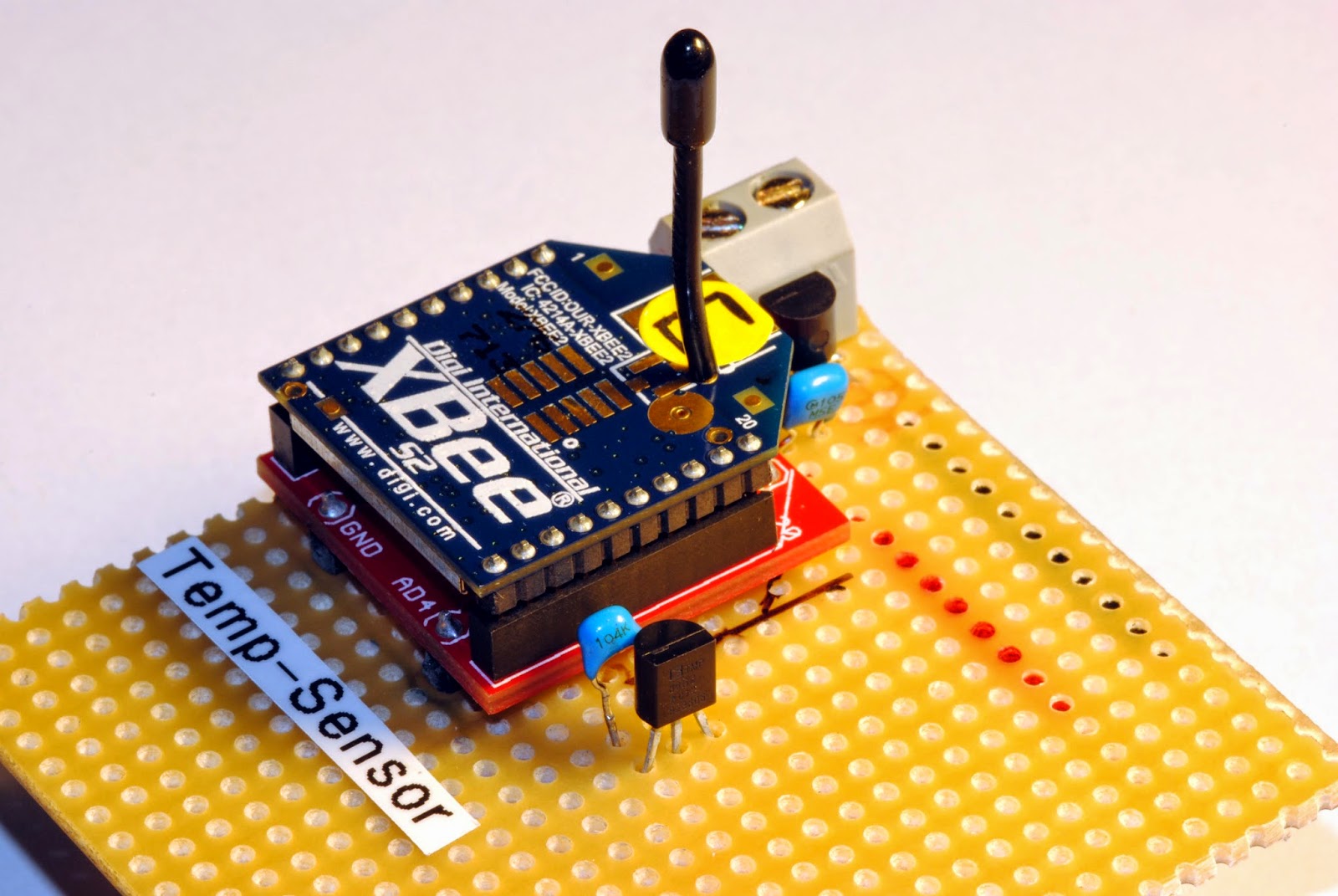
The actual remote sensor has the components just soldered to a stripboard (which works for years now outdoors without any problems). For voltage regulation I use the low quiescent current LDO from Microchip MCP1700-3302E (3.3V, TO-92 style, ~1µA quiescent current consumption). There are 1µF ceramic capacitors both on the raw voltage input and the regulated output (just followed the typical application advice on the datasheet).
The temperature sensor TMP36 is wired to Ground, the Vout is connected to pin 20 of the XBee (AD0/ DIO0/ commissioning button) and Vin is wired to pin 13 (ON/ SLEEP).

The trick with consuming power for the temperature sensor only when the XBee is awake is to wire it to pin 13 (ON/ SLEEP) which is only powered when the XBee is awake.The sensor takes about 50µA when powered and is fast enough to get a temperature measurement while the XBee is not sleeping and takes samples from the AD0-Input (pin 20 XBee).

Temperature sensor on stripboard
My sensors are all powered with three AA cells for now and there is enough room from about 4.8 volts when full and fresh to 3.3 volts when it hits the regulated voltage. The sensor even works below that because I think the supply just gets pulled through the voltage regulator when at or below the regulated voltage.
The circuit draws only about 2.3µA when the XBee sleeps and about 40mA when awake but only for a very short amout of time. So the batteries last about are year or longer.


Software
 There is not much software involved beside configuring the logic on the XBee. Those are my settings:

SENDER: (REMOTE SENSOR )
END DEVICE
ATID 2001 (PAN ID)
ATDH 0
ATDL 0
ATD0 2     pin 0 in analog mode with TMP36
ATIR 3E8  sample rate 1000 millisecs (hex 3E8)
ATSM 4     sleep mode cyclic sleep mode
ATSN B     number of sleep periods (hex B = 12 decimal)

ATSP 7D0  sleep period (hex 7D0 = 2000 ms * 10 = 20 seconds)
ATST 7D0  time before sleep 2 seconds (hex 7D0 = 2000 ms)

Output on a custom made display-box for the kitchen with bus schedule
So the sensor is configured to sleep for four minutes (roughly, the oscillator in the XBee circuit seems to be either imprecise or temperature sensitive) then waking up for two seconds, powering the temperature sensor, sampling two times and then go to sleep again. That's all it does. Voila!

There is still room to improve the project. For example one could add an energy harvesting module to the circuit so that no batteries are used to power the device. Another nice feature would be to take a measurement of the actual battery voltage, which could be done with a simple high resistance voltage divider on one of the analog inputs. It might also be clever not to wire the temperature sensor to pin 20 which is also the comissioning button just in case your XBee is reluctant to wake up.