7/07/2016

ESP32 Article

ESP32 in Make: Magazin Germany

I wrote an article for the german edition of Make: Magazin (so yes, it's only in german language) about the upcoming ESP32. It's about the differences to its "little brother" ESP8266. I'm also explaning how to install and work with both the Arduino IDE and Eclipse giving some basic programming examples.

Basic electronic setup of ESP32

The ESP32 will be available in August/ September according to Espressif. Looks like we might have to wait for developer boards a few months more.

6/02/2016

ESP32 programming examples

Some code examples for the ESP32 (ESP31B) beta developer board from Espressif


ESP31B developer board
I'm currently evaluating the ESP31B developer board (ESP-WROOM-03) I got from Espressif more in depth and began to write some example code for the new chip ESP32,which is due in August/ September according to the chip manufacturer.

You can find the code in my github account here. It's work in progress and I will add more code over time.

I posted some high-resolution photos in this blog entry.

5/26/2016

9 reasons why "Big Data", "IoT" and "Smart Home" might be so dangerous...

...or delicate at least


Not only buzzword paradise (for the big companies) - but big money

Data streams

Working for years on making "things" communicate with "machines" and hence putting them in the augmented live of ourselves there is always the discomfort of the consequences of one's actions.

I wouldn't dive any deeper into any horror scenario resulting of this or serve a model for another (american) dystopian movie.
Let us instead analyse hard facts in form of ONE single data stream only being available as a graph so that you can judge yourself what could be a realistic outcome of the "Internet of Things" where already billions and billions of devices are connected worldwide.

Day 18 since seed
As you can read in my blog I'm currently tinkering with the new IKEA Krydda indoor gardening stuff. Nature should be allowed to run its course? Sure, but adding electronics always makes fun and often gives much more insight to things you didn't see before (did you ever take a thermal picture of something? See examples here). I'm putting the data into the "Internet of things" here so you can see 24/7/365 what's happening in my gardening paradise at home.


Day 18 since seed
So let's see what we can tell just from one and only one graph ("data stream"). For the beginning we assume we even have no absolute numbers like YOU do it everyday 24/7/365 with your smartphone, PC, car etc. sending your life ("numbers") to the big data centers in Silicon Valley and everywhere in the world analyzed by the smartest algorithm programmers available and fastest electronic brains existing.

ONE graph


1. Flatline

Nothing happening and therefore not interesting while there is nothing to see in the graph aka as a "flatline"? Wrong! Nothing happening could mean you are sleeping (now "they" can tell your sleeping habits if there are more time periods to sample) or find out that the apartment is not occupied (welcome burglars!). I do not even need to know the type of data (like temperature or electric power consumption).

2. Controlled curve

There is something ramping up for a certain amount of time in a very constant way. First guess: Might be a (electronic) device not a human action. Maybe the heating system? Without knowing the data type (8) it's hard to tell. But if I only know once what type of device this kind of ramping-up produces, I could draw conclusions to every other data stream from anyone I get with the same pattern.
In this case it's the wake-up mode of a Philips Hue lamp over a time frame of thirty minutes (7). Linked to number (6) you might even tell the lamp type or color. Hackers welcome if they know which devices are in your home! And your next ads in your browser/ app might be related to the lamps. You also need a light strip from Philips?

3. Elevated flatline

The previous phase is completed. Might there be something happening next or what? Compare 1, 2 and 3 over more periods and you already get very interesting details on sleeping and living habits and hence patterns.


4. Digital

Something gets elevated very quickly like a 0 to 1 transition. Knowing the type of data (8) it's not hard to judge what happened. More insight into your living habits if linked to (7) time and date. Just from one (mechanical) action. Imagine all the mechanical switches are replaced with "intelligent" ones.

5. Analog

Something "irregular" is happening. Typical analog data of very fine granularity and therefore very helpful. Put the data in the big electronic brains and compare it to typical analog data (e.g. weather data like temperature, wind, cloudiness) and there will be a meaningful outcome - for sure. If you have the data type (6, "light intensity"), (7, "time"), (8, "light") you do a favor to the wallets of the big data center owners because they only need to buy little computing time. Now "they" not only know your sleeping habits, living pattern, your electronic devices but also where you live.
No they did not need your GPS signal you are always sending with your smartphone or the WiFi data you are allowing them to track.

6., 7. Goody: Scaling/ reference

We are still not talking data streams with exact (absolute) numbers but only a single graph we get over time. Add goodies like a scale or reference to make it easier. But be assured clever algorithms are already bored if you give them such kind of a cheat sheet.

8. Data type

Oh "they" also know what kind of data you are delivering - thank you for willingly helping to get the graph-only data even more interpretable.

9. Big data

You are adding more linked data like temperature, humidity and a data stream with numbers? You are already toast, this only adds to the finer granularity of your being. And always remember: you still have not told someone one single (unencrypted) letter - like you do everyday putting your most intimate details on messengers like "Whatsapp" or by sending your data into the "cloud".

Conclusion


We only examined ONE very simple data stream in form of a graph. Only from the pattern of one simple, single data source you can tell a lot of stuff. Much more then mentioned above - we only scratched the surface in interpreting data. That's why educating people as "Data Scientists" exploded in recent years.

Now imagine ALL the data YOU (and of course ME!) are sending every second into the enormous data cloud! Judge yourself what could happen and what we should do in the future regarding data aka the "Internet of Things". For the moment OTHER people are getting YOUR data and earning a lot of money from it or even worse.

What we should do and behave? Proposals very welcome! For the time being enjoy this "paradise" of "Big Data" - and did you just switch your light on?

5/23/2016

Web dashboard for IKEA Krydda

Firmware sketch for ESP8266 with web dashboard on adafruit.io

Adafruit.io dashboard
Dashboard for my growth system
To monitor your cultivation unit from local/ everywhere I wrote a sketch to both send the actual light intensity values via the serial port and to adafruit.io which is a nice web service for displaying data in the internet (of things).

Currently only the light value is displayed and more sensors will be added in the future.

You can see the actual values of my Krydda system here.
 
More information on how to set up your own dashboard on adafruit.io can be found here

UPDATE 23-5-2016: Added temperature and humidity with the Sensirion SHT21 sensor.

5/22/2016

IKEA hydroponics - First sensor for ambient light

Sensor measures light intensity for the plants

Lights sensor BH1750FVI connected to a ESP8266
The first sensor for my IKEA hydroponics project is a ambient light sensor (BH1750FVI) which will measure the light intensity on the plant bed in both the seed and cultivation unit. It is currently connected to an ESP8266 - a DIY-friendly and hacker-famous microcontroller with WiFi on board. I wrote a library for the light sensor which works with both Arduinos and ESP8266. You can find it here.

Germinated seeds in cultivation unit
The example sketch in the repository currently measures only the actual value of the ambient light. In future versions this sensor will be responsible deciding if and how long the IKEA LEDs have to be switched on depending on the overall light which fell on the plants. There will also be an uplink to a web-service (like Thingspeak or adafruit.io) where all the values are monitored in real time on a nice looking dashboard and will be accessible from everywhere.

In the meantime the seeds that germinated changed their habitat to the cultivation unit.


5/12/2016

Project to control IKEA hydroponics Krydda/ Växer

I'm starting a new project with the brand new indoor gardening system from IKEA which is named "Krydda"/ "Växer".

This is a picture of the initial seed:

Initial seed day 0
Planned items are to control and optimize growth with a microcontroller/ embedded system and sensors (light, humidity, temperature, CO2, water level etc.) utilizing automated lighting and water refill with the new IKEA Krydda/ Växer system.

You can follow the project here and at my github repo

4/18/2016

Update: ESP8266 Breadboard Adapter Board


I designed a single-sided ESP-12/ ESP-07 breadboard adapter PCB which will be easy to etch and solder for anyone who loves to play with the ESP8266 on a breadboard like me. 

There are different designs of the breadboard adapter:
There is also a nice 3D-printed socket from Moritz in his github account to easily program (lots) of ESPs without the need to solder them at all.

Features are:

  • Fits ESP-12 and ESP-07 module
  • Single-sided self-etchable design
  • Few, cheap parts in SMD
  • Breadboard-style - one row on each side accessible
  • Vin >4.8V (max. 12V) input possible with 3V3 onboard voltage regulator (with two capacitors 10µF)
  • RST, CH_PD, GPIO0 with 4k7 pull-up resistors on board (resistors can be omitted if remote access of those GPIOs is needed)
  • GPIO15 with 4k7 pull-down (see above)
  • Tactile switch connected to GPIO0 to get into flash mode
  • Reset switch
  • Solder bridges for DTR, RTS lines to enable automatic flashing without having to press buttons

Parts needed:

  • ESP8266-12/ -07 module
  • 1x Voltage Regulator (e.g, AMS1117-3.3V, 800mA)
    Kit
  • 2x 10µF SMD ceramic capacitors
  • 4x 4.7k SMD Ohm resistors
  • 2 1k SMD Ohm resistor
  • 2x 4*4mm SMD tactile switch
  •  2x 1*8 pin header (pitch 2.54mm)
  • 12MHz crystal
  • 2x 22pF capacitors
  • Micro USB connector
  • 100nF capacitor
  • CH340G USB to serial IC
Remember to put three jumper wires on the bottom side as this is only single sided. See Eagle files for connections.

4/09/2016

Raspberry Pi 3 "Echo"

Building an Amazon Echo similar device out of a Raspberry Pi 3


I recently worked as an electronics hardware developer on a new smarthome system which is designed to have speech recognition as a way of controlling devices.


Over the course of researching soft- and hardware for this purpose while in Silicon Valley I also tested and reverse engineered the "Amazon Echo" - an electronically very well designed device and a huge success for one of the in-house manufactured devices from the electronic commerce and cloud computing company.

The latter also lays the groundwork for Amazon Echo and the speech recognition called "Alexa" utilized in the round tower like gadget. With a price tag of $180 and - more important - not yet available to customers outside the US I was quite happy back in Europe to see a github repo to allow implementing an Amazon Echo similiar device and especially speech recognition on cheap hardware like a Raspberry Pi.

I bought the quite new Raspberry Pi 3 - even if the github repo uses a Pi 2 - expecting some minor issues, what turned out to be true. A big help was to browse the "issues" related to the repo.

In short I avoided to install a new JDK because it already comes with new Raspian Jessie image. I put on the newest version of Node.js, used the WiFi which is onboard with the RasPi3 and tested different microphones because the one suggested on the github repo has some bad reviews. That's basically all I deviated from the original installation instructions, which worked out very well.

After only two hours or so everything was set up without problems. In the video below and for the first tests I used a webcam with an integrated microphone, a Logitech QuickCam Orbit AF, which I had lying around while the dedicated USB microphone was ordered but had not arrived.


Identifying the microphone chipset

The problems began when I got the new USB microphone, a "Lerox USB microphone" ordered - of cause - from Amazon. In the beginning I had barely no success getting "Alexa" recognizing my commands. I had pulsing sounds (which I hadn't before) and the speech recognition stopped before I could even tell the whole command. The microphone identifies as a "C-Media Electronics device" with a CM108-chipset.

Three efforts led me to success:
Microphone configuration with "alsamixer"

1. I adjusted the recording settings of the microphone with "alsamixer". It turned out to be a good setting (at least for the microphone used) when it is set to the highest "green" level available.

2. I changed the USB power supply for the Raspberry Pi 3. This is where the klicking sound while recording the commands came from. Might be more a bad design of the microphone than of the power supply, as I used a high quality PSU first.

Editing settings for the microphone
3. This might be the most important setting fiddling with microphone problems: I adjusted the values in the java source code (../samples/javaclient/src/main/java/com/amazon/alexa/avs/ASVApp.java) for "ENDPOINT_THRESHOLD" (minimum audio level threshold under which is considered silence) and "ENDPOINT_SECONDS" (amount of silence time before endpointing). Default was 5 respectively 2 which I changed to 7 and 4. After a "mvn install" to do a new build and the call "mvn exec:exec" it now almost works like the original Amazon Echo.

Audio device settings

4. You might have to set your microphone as default input source. You can do this by choosing "Menu -> Settings -> Audio Device Settings" selecting your soundcard (microphone), add elements and make the microphone the default. This is where you can also set the gain or any additional elements like auto gain control (AGC) when provided by the soundcard/ microphone. As far as I understand choosing and setting the microphone with "alsamixer" does the same but I'm not sure about it.

The next thing I will implement is the invocation with a spoken command like the Amazon Echo - where you can choose between "Alexa" and "Amazon". As far as I could reverse engineer it Amazon solves this with a bunch of Texas Instruments TLV320ADC3101 92dB SNR Low-Power Stereo ADCs, which have an integrated miniDSP and I guess this is where they put the algorithms (aka "magic") for recognizing the invocation command while after this streaming the rest to their cloud servers. You find a lot of technical details of the Amazon Echo in this awesome ifixit Amazon Echo teardown .

EDIT 4-10-2016: Added instructions of Elton "Eddie" Hartmans fork to the installation on my Raspberry Pi 3 and it's now possible to start voice commands either by clicking the button on the JAVA-GUI or by pressing a switch connected to the GPIOs of the Raspberry Pi.

EDIT 4-25-2016: If you want to use bluetooth speakers follow this awesome tutorial from David Roberts. Unfortunately I wasn't able to connect my microphone which is embedded in my bluetooth speaker BoomStar BT NFC X yet.

12/26/2015

ESP32 beta breakout board

Breakout board for the new ESP32 beta module

Just a little addition to the previous post. I made some photos of the breakout board which was accompanied with the ESP32 beta module. Quite interesting is the thermal pad which is connected to ground. This might be important to solder to the beta module if you clock the chip higher than the standard 80MHz.

Breakout board top pcb
Breakout board bottom pcb

12/25/2015

ESP32 beta module HiRes pictures

ESP32 beta test module


I'm glad to be one out of the 200 beta testers for the new Espressif ESP32-chip (it's labeled ESP31B, the obvious name for the beta-ESP32?), which is brand new and adds some functions like Bluetooth (Low Energy) and a second core to the cheap-and-easy ESP8266.

Before soldering the module I took some photos with my Micro Nikkor 105mm/2.8f and stitched them together with Microsoft ICE. This results in photos of about 4400x3100 pixels, which means a quite big download if you click on the preview pictures.

If you want to have a look what I'm currently developing for a new smart home platform using the ESP8266 you can find more info here (CO2 sensor module) and here (Experimental Platform) which is currently in alpha testing.

Concerning the ESP32 Hackaday has a nice news flow and Limor "Ladyada" Fried from Adafruit made a detailed video on the new beta module.

If you are a german reader then you can read my article on the ESP8266 in the current edition of the german Make: magazine (10 pages).

So enjoy the the new module and stay tuned for more news.

Click here for the HiRes pictures: top (~7MB), bottom (~10MB).

ESP32 beta test module top

ESP32 beta test module bottom

2/08/2015

ESP8266 breadboard adapter board

This is an old design of the breadboard adapter. Please look at this blog post for the recent design.

I designed a single-sided ESP-12/ ESP-07 breadboard adapter PCB which will be easy to etch and solder for anyone who loves to play with the ESP8266 on a breadboard like me.

Eagle files are in my github repo

Features are:

* Fits ESP-12 and ESP-07 module
* Single-sided self-etchable design
* Few, cheap parts in SMD
* Breadboard-style - one row on each side accessible
* Vin >4.5V (max. 7V) input possible with 3V3 onboard voltage regulator (with two capacitors 10µF)
* Power-indicator LED
* (Schottky-) Diode as reverse polarity input protection possible (solder 0 Ohm resistor or just connect the two pads for no protection)
* RST, CH_PD, GPIO0 with 4k7 pull-up resistors on board (resistors can be omitted if remote access of those GPIOs is needed)
* GPIO15 with 4k7 pull-down (see above)
* Tactile switch connected to GPIO0 to get into flash mode
* Single post for 3.3V output near voltage regulator

Parts needed:

  • 1x Voltage Regulator (e.g, AMS1117-3.3V, 800mA)
  • 2x 10µF SMD ceramic capacitors
  • 4x 4.7k SMD Ohm resistors
  • 1x 330 SMD Ohm resistor
  • 1x SMD-LED (1006)
  • 1x 4*4mm SMD tactile switch
  •  2x 1*8 pin header (pitch 2.54mm)
  • optional: 1x Schottky-diode SMD
This is the actual revision 1.0 - improved for:

* Antenna part now protruding the PCB (no traces below antenna)
* Wider traces
* Schottky diode for reverse polarity protection
* 2x 10µF ceramic caps for input/ output of AMS1117
* Single post for 3.3V Output near voltage regulator

2/04/2015

ESP8266 - inexpensive IoT

Presentation ESP8266 - Basics and programming examples


On February 2 I had a short presentation at the Makerspace Attraktor in Hamburg on how to use and program the new chinese IoT-IC ESP8266.

The space was quite crowed with more than 40 listeners interested in the new and very inexpensive module with a great range of programming possibilites.

You can find the presentation (pdf in german) here


If you want to stay in touch with new projects or blog entries you can follow me on twitter

10/06/2014

Basics about Lithium rechargeable cells

Presentation: Basics, charge and control circuits/ ideas for singe cell lithium rechargeable batteries


Lithium cells are quite powerful
On October 6 I had a short presentation at the Makerspace Attraktor in Hamburg on how to work with rechargeable lithium cells.

A lot of information has to be considered when working with rechargeable lithium cells. Beside the basics, I went into information about the typical charge and discharge characteristics and some circuits and ideas on how to charge and control those cells.


You can find the presentation (pdf in german) here


If you want to stay in touch with new projects or blog entries you can follow me on twitter

4/09/2014

XBee remote temperature sensor

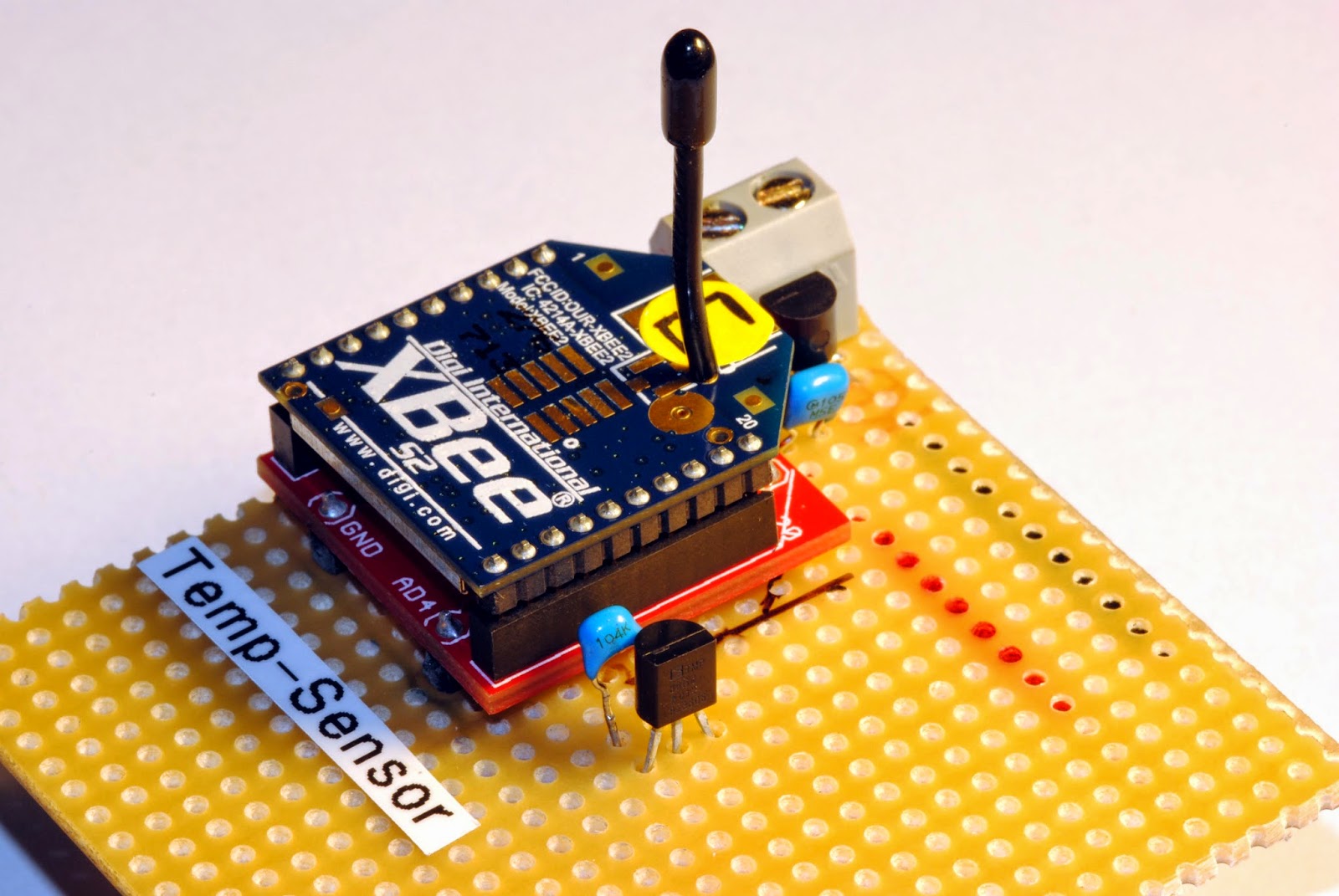
There were some questions over time on how the remote sensors on my XBee network are actually wired up and I discovered that I only showed the sensor as is and never explained the wiring. So now this is done with this post and a breadboard picture made with Fritzing:

Remote temperature sensor with XBee

Hardware
The actual remote sensor has the components just soldered to a stripboard (which works for years now outdoors without any problems). For voltage regulation I use the low quiescent current LDO from Microchip MCP1700-3302E (3.3V, TO-92 style, ~1µA quiescent current consumption). There are 1µF ceramic capacitors both on the raw voltage input and the regulated output (just followed the typical application advice on the datasheet).
The temperature sensor TMP36 is wired to Ground, the Vout is connected to pin 20 of the XBee (AD0/ DIO0/ commissioning button) and Vin is wired to pin 13 (ON/ SLEEP).

The trick with consuming power for the temperature sensor only when the XBee is awake is to wire it to pin 13 (ON/ SLEEP) which is only powered when the XBee is awake.The sensor takes about 50µA when powered and is fast enough to get a temperature measurement while the XBee is not sleeping and takes samples from the AD0-Input (pin 20 XBee).

Temperature sensor on stripboard
My sensors are all powered with three AA cells for now and there is enough room from about 4.8 volts when full and fresh to 3.3 volts when it hits the regulated voltage. The sensor even works below that because I think the supply just gets pulled through the voltage regulator when at or below the regulated voltage.
The circuit draws only about 2.3µA when the XBee sleeps and about 40mA when awake but only for a very short amout of time. So the batteries last about are year or longer.


Software
 There is not much software involved beside configuring the logic on the XBee. Those are my settings:

SENDER: (REMOTE SENSOR )
END DEVICE
ATID 2001 (PAN ID)
ATDH 0
ATDL 0
ATD0 2     pin 0 in analog mode with TMP36
ATIR 3E8  sample rate 1000 millisecs (hex 3E8)
ATSM 4     sleep mode cyclic sleep mode
ATSN B     number of sleep periods (hex B = 12 decimal)

ATSP 7D0  sleep period (hex 7D0 = 2000 ms * 10 = 20 seconds)
ATST 7D0  time before sleep 2 seconds (hex 7D0 = 2000 ms)

Output on a custom made display-box for the kitchen with bus schedule
So the sensor is configured to sleep for four minutes (roughly, the oscillator in the XBee circuit seems to be either imprecise or temperature sensitive) then waking up for two seconds, powering the temperature sensor, sampling two times and then go to sleep again. That's all it does. Voila!

There is still room to improve the project. For example one could add an energy harvesting module to the circuit so that no batteries are used to power the device. Another nice feature would be to take a measurement of the actual battery voltage, which could be done with a simple high resistance voltage divider on one of the analog inputs. It might also be clever not to wire the temperature sensor to pin 20 which is also the comissioning button just in case your XBee is reluctant to wake up.

3/13/2014

Malaysia Airlines MH370 whereabouts and the technical part of it

The mystery of the whereabouts of Malaysia Airlines flight MH370 continues and all my thoughts go to the family members having relatives on board of the disappeared Boeing 777-200.

But there is also technical part of the whole story and regardless of the outcome it's worth having a look at the different systems which are involved electronically.
There are four main systems which provide communication between an airplane and the ground. The oldest one, which helped the british army to identify their german counterparts, is the


Primary Radar

High frequent impulses are sent out by a (ground) station into the air and if they are deflected they echo back to the receiver at the (ground) station. The time the signal runs can be calculated and from that the distance and direction of the "object" is derived.
Primary radar signals have to be interpreted so it's sometimes not easy to judge if the "object" is a plane or a flock of birds. There are also limits due to the range of the radar waves and other factors like weather.
Some producer of flying (military) objects - stealth planes - even use their outer shape to avoid any de- or reflection of the radar waves.
To support the findings of the passive primary radar most of the planes, helicopters etc. send out an active transponder signal which is termed

Secondary Radar

Where the word "radar" stands for an active transmission of a signal coming from aboard a flying object. Well known as "transponders" the device sends an active signal which can be of different quality. The earliest systems gave an identifier or answer code (aka "Squawk code") so that the signal of the primary radar and the received signal of the transponder could be matched.
Today a system known as "ADS-B- Automatic Dependent Surveillance - Broadcast - is used in many (commercial) airplanes. Once the systems on the plane are on, ADS-B is also automatically activated. Already on ground the system gets automatically interrogated by ground (radar) stations so that the signals can be matched. But those newer systems not only give an identifier, but also lots of other data like speed, altitude, heading and more. The Boeing 777-200 MH370 is equipped with those systems. The range also depends both on the (height/ distance) of the airplane and the quality of the receiving (ground) station.
The frequency of ADS-B is 1090MHz.


Voice Radio Transmissions

Even if many of the processes in aviation are automatically done there is still a lot of live voice communication between pilots an (ground) stations. This is done mostly on VHF (Very high frequency). The normal air radio frequencies are between 108 and 137 MHz. Military often uses other (higher) frequencies.
As with all high frequencies the transfer of messages underlies technical constrains like range, weather, power of the sender, height, and receiver sensitivity. So in some parts of the world there still have to be used less sophisticated radio signals to get contact to the ground.

ACARS - Aircraft Communications Addressing and Reporting System

Another active system is known as ACARS  - Aircraft Communications Addressing and Reporting System. It does what the name implies - it actively, automatically, un-interrogated sends data live to the ground or up to a satellite. Data can be of any quality - from simple status messages to extensive data reports from systems on the plane. Allmost all commercial aircrafts send those data to their headquarters relayed by radio stations around the world.
As allegedly done and reported by the Wall Street Journal the MH370 sent (engine) data for hours into the flight. Depending this is true it is still the question of what quality the data was.
-UPDATE Malaysian officials have told there were no ACARS radio transmission after losing contact to MH370. Last ACARS transmissions were at 01:07AM local time -
The radio transmissions are done in some of the air band frequencies so they underlie the some constraints as mentioned above.

Then there are sensors and radio transmissions more or less independent on the before mentioned systems like the one of the jet engines, which are capable of sending sensor data without using the ACARS system (e.g. http://www.rolls-royce.com/about/our-technology/enabling-technologies/engine-health-management.aspx#sense). Those were of special interest in the MH370 case because there were transmissions long after disappearing of the plane and some attempts of triangulation to get a possible location of it.

In case of an emergency EPIRBs - Emergency position-indicating radiobeacon stations - are automatically activated. They are also constrained in respect to range and especially the time (about 30 days) they are able to send signals. There are a lot of systems for different use cases available (More info: https://en.wikipedia.org/wiki/Emergency_position-indicating_radiobeacon_station).

Finally there are other means of identifying flying objects like satellites which are capable of visual or radio tracking, flying radar/ radio stations like AWACS-planes (Airborne Warning And Control System) and other and more secret ways to identfy objects in the airspace.
But those are special ways and normally not involved with commercial aviation.

Updated: 5-20-2016

2/17/2014

New Project: DIY 3D-Filament Extruder

Filament extruding machine

I'm a lot into 3D-printing the last months so it was quite silent with news in the blog. Staring at plastic building up in layers so thin you can barely see them is very fascinating as it builds up a new dimension one is not used to see. But the plastic material called "filament" for 3D-printers is neither very cheap nor you have a great choice of colors or materials (yet).


Layer as fine as 10 micrometer printed with my Ormerod 3D-printer
So my very new project is building a DIY 3D-filament extruder. Yes, there are already projects like Filabot and Filastruder out there, but I could not find real DIY projects among them.

It happened that I worked as a holiday job at a plastic recycling factory almost thirty years ago, that did exactly what I'm planning to do now - extruding filament from pellet like material. It's a personal challenge to return to this.

It's not only a challenge to build such a machine but also to get it producing high quality materials that print either very thin layers (see photo) or different materials with certain characteristics, that can be easily reproduced in every aspect like quality, diameter etc.

So stay tuned for the developments here.

DIY  Project "Print your laser"

I'm also working on printing the 3D-parts for Markus' (same name but not me ;) ) awesome print your laser project, with other people at our Makerspace Attraktor in Hamburg. Markus wants to build a DIY CO2 laser from parts readily available and of course as cheap as possible. At the moment we are testing the end caps for the plasma tube and getting them as airtight as possible.

It's fascinating how 3D-prinitng opens a whole new way to design and produce things like twisted tubes buried into parts which would be impossible to make with conventional and relatively affordable tools like a lathe or CNC milling machine. Of course it's possible to do things like this for quite some time as there a professional and very expensive ways to do this - but DIY-wise and making with low budget is the real new way getting things done.

But it still needs to design the stuff with CAD-programs (lots of open source like OpenSCAD available), prepare it for 3D-printing (like slicing the 3D-models), getting the right materials and troubleshoot the prints for their very application. 3D-printing for everyone is still a bit out there.

In the video (timelapse) above you can see a small part of the end cap for the laser tube printed on my new Ormerod 3D-printer from RepRapPro.


8/08/2013

How-to convert a cheap IKEA Samla box into a Maker-box

Cheap box for makerstuff converted into lockable case


IKEA samla box
I really like those cheap IKEA Samla boxes. They are very well suited for a lot of stuff especially when you move makerstuff to the makerspace or friends. Available in different sizes and stackable (you can stack different sizes on top of each other) and a separate lid you can also store stuff at home.

But one thing what was always annoying me is that you can't fix the lid to the box or even more could lock the box. So I designed three cheap ways to make the box lockable and secure.

Old PC screws, wire an rawlplugs
Velcro to join lid and case together
One way is to take some old spare PC screws and wires, drill holes into the lid and case and join the wire and the rawlplug with a screw. You then can secure the lid to the box by pushing the rawlplugs through the lid and box. In order not to loose the plugs you can secure them with wire and a screw.


Suitcase lock
Much simpler but a little bit more costly is to use some velcro. A velcro tap on the lid and on the box connected by a strip of velcro secures the lid to the case but this solution is less rugged.


If you have to secure the box against unwanted access, just drill a hole in one side big enough to apply a cheap little suitcase lock. The other side is secured by a keychain ring. Et voilá. Stuff secured.

8/05/2013

Power supply for remote sensors

Presentation: How to supply power to microcontrollers/ (remote) sensors with low dropout (LDO) voltage regulators and batteries


"Classic" 7805 Voltage regulator
On August 5 I had a short presentation at the Makerspace Attraktor in Hamburg on how to supply independent power to devices like standalone microcontrollers or (remote) sensors.

 The talk gave some comparison about different low dropout voltage regulators which are by design very well suited for battery powered devices. Decision finding on what parts are most suited and design considerations for independent sensors were explained detailing a remote temperature sensor project I'm working on for about two years now.

XBee temperature sensor


You can find the presentation (in english) here

If you want to stay in touch with new projects or blog entries you can follow me on twitter

7/30/2013

Arduino and Android control speed and direction of RC Surfer

Accelerometer sensor controls throttle and rudder


My RC surfer project (see last Blog entry) evolves into much more work than thought and the last addition is the control of the dc motor speed and the rudder with the Android phone.

Using the accelerometer sensor x- and y-axis values which are sent via bluetooth to the Arduino board I can in-/ decrease the speed of the motor by turning the phone up and down. To control the rudder I have to flip the phone to the left or to the right.

The reaction time with the first code on Android/ Arduino was kind of slow. I had to optimize the code and now it reacts almost in real time. Only the voltage value which is displayed on the phone is jumping when there is (too) much load on the system. I might have to add some isolation to the Arduino power supply to avoid too much noise when the motors draws much current.

The next thing I will do is to design a PCB which fits into the free space of the RC surfer in the forward compartment. So it's EAGLE time!

7/22/2013

Temperature sensor current consumption

1 year with batteries - temperature sensor project

Temperature sensor with alkaline batteries
Just a quick update on my XBee/ LCD/ temperature sensor project which I originally started in 2011 (last blog entry: XBee temperature sensor project ). I  had to replace the already used battery cells which I put into the sensor about one year ago (August 31 2012) because I got some timeouts on my receiver. The
voltage came down to 3.34 volts and this is a point where the low dropout regulator (MCP1700) keeps quit working sometimes even when the load is only about 25 mA every four minutes when the XBee (end device, sleeping) sends the temperature data to the coordinator.

Voltage development temperature sensor
The three battery cells had a voltage of around 4.1 volts when I started using them for the sensor, so they were already down from their original voltage/ capacity which is around 1.5 volts per cell for unused batteries.
Why did I use used battery cells and not new ones? Because they were lying around and I was wondering how long some spare, already used cells would last during time and different weather conditions. And they lasted almost one year!

The temperature sensor is located outside and we had temperatures of around -15 to +30°C during the year. The chart you see is far from scientificly accurate but gives you a raw picture of the voltage curve for those cells (GP super alkaline).

Next I will replace the batteries with some rechargeable batteries. There are some nice energy harvester ICs on the market - maybe this will be the next power supply for my sensors. Stay tuned.